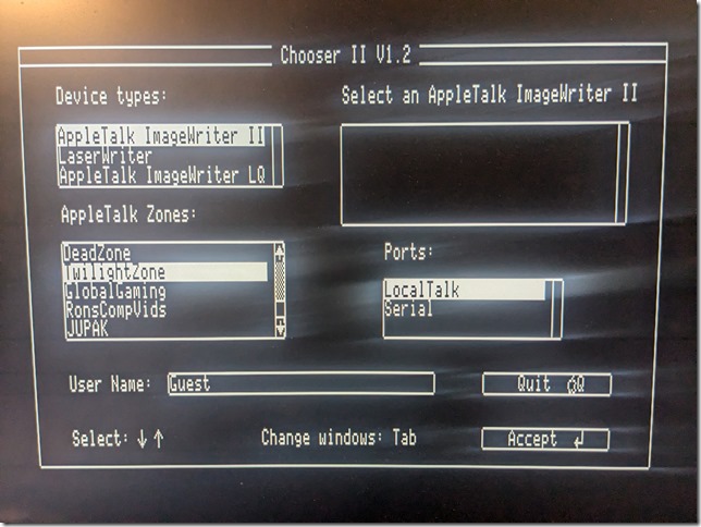
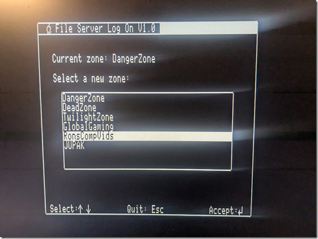
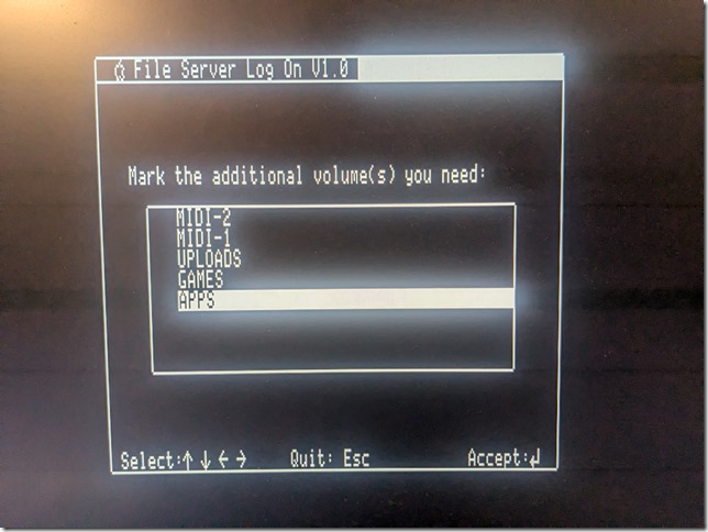
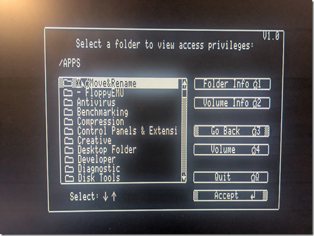
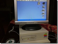
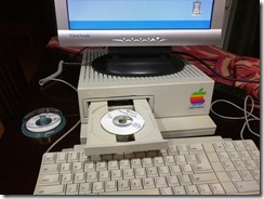
Apple IIgs Clean Install of System 6.0.1 on BlueSCSIv2

About two or three years ago, the BlueSCSI open-source boards came about from the retro-computing community.  These devices have a SCSI interface, either the DB-25 DSub or the 50-pin IDC connector, and they emulate SCSI devices via some “disk” images in a FAT32-formatted microSD card.

I was partially on hiatus from the retro-computing community already about 5 years (I still am), but I could not ignore the developments happening in SCSI emulation.  I have always been a proponent of SCSI, more on that in a future blog post.  Last year, I bought several of the BlueSCSIv2 devices and have started using them on my Apple IIgs and my 68k Macs.  I would just copy the backup images of partitioned and ProDOS-formatted drives into the microSD card, and the Apple IIgs would boot from the BlueSCSIv2 device without any issues.
There are numerous drive images publicly available for download and use as a starting point for running GS/OS without having to go through the standard installation process.  But what if you want to create your own hard drive installation from the official installer diskettes?  System 6.0.1 installation officially came in 6 800KB 3.5” diskettes, and the images of those diskettes are readily available in the Internet (one mirror here).
Possibly the most straightforward way is to run an Apple IIgs emulator (e.g., kegs, gsport, etc.), mount the installer diskette images into the virtual drives of the emulator, and perform a hard disk installation in the emulator.  The resulting virtual disk is often in a form that can just be copied over to a microSD card and used in BlueSCSIv2.

However, even without an emulator, you can perform a hard disk installation on your Apple IIgs equipped with a SCSI card and the BlueSCSIv2.  The BlueSCSIv2 is able to emulate a SCSI floppy device.  There are real SCSI floppy devices manufactured in the `90s and they are now getting rare.

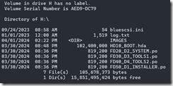
In my Apple IIgs, I assigned 0 (zero) as the SCSI ID of the SCSI card inserted in Slot 7, just to be different from the default SCSI ID of 7, configured via some switches on the card.  That leaves emulating up to 7 other SCSI devices in BlueSCSIv2.  For the hard disk image, just create a zeroed file of the desired size.  In my test, I created an empty 100MB file.  Using the BlueSCSIv2 naming conventions, I assigned this 100MB file to SCSI ID 1.  Four of the installation diskette images are assigned to SCSI IDs 2-5.  I only used the first four diskettes, but you could just as readily assign the remaining two diskettes to SCSI IDs 6 and 7.

The following screenshot is from a listing that mounted the 16GB microSD card on a Windows machine:
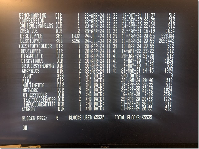
AppleIIgs-BlueSCSIv2-Install-0

On initial power up, bootable SCSI devices are inspected from the highest SCSI ID going downward.  That is why I assigned the first diskette, the Installer diskette, into the highest SCSI ID of 5 in the group.

AppleIIgs-BlueSCSIv2-Install-1AppleIIgs-BlueSCSIv2-Install-2AppleIIgs-BlueSCSIv2-Install-3AppleIIgs-BlueSCSIv2-Install-4AppleIIgs-BlueSCSIv2-Install-5
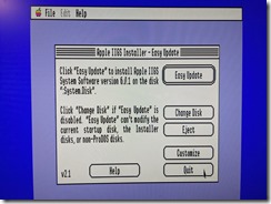
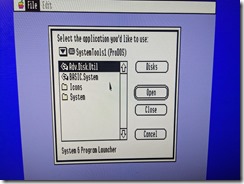
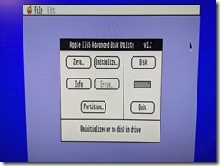
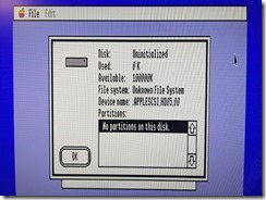
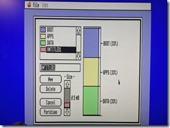
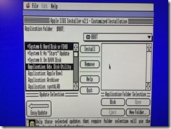
Upon boot, the standard Installer runs and you can select options for a hard drive installation.  Since the 100MB drive is still unformatted, you want to quit the Installer and run Advanced Disk Utility, located in the System Tools diskette (Diskette 3).  That will allow you to partition the 100MB and initialize each partition with the ProDOS file system.

AppleIIgs-BlueSCSIv2-Install-6AppleIIgs-BlueSCSIv2-Install-7
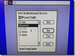
You can then go back to the Installer and proceed with the hard drive installation.  Because the four (or six) diskettes are all assigned to separate SCSI IDs, they are all mounted and there will be no prompts for swapping diskettes, as it would when installing from an external 3.5” drive.

AppleIIgs-BlueSCSIv2-Install-8
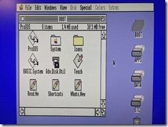
Within just a few minutes of installation, your 100MB will be ready and bootable.  One thing I noticed when the installation was completed was that the “floppy” device (SCSI ID 5) that initially booted the system seems to be in an “ejected” state, and rebooting would boot from the freshly installed 100MB drive.  Also, once you reach GS/OS, you will notice that the “floppy” devices are not mounted on the desktop.  Perhaps GS/OS is looking for a partition map on all the SCSI devices.  The floppy diskette images definitely do not have partition maps, and could be why they are not recognized or mounted.

However, upon a power cycle of the machine, it would again boot from the highest bootable SCSI ID (SCSI ID 5), which is the Installer diskette.  To consistently boot from the hard drive, it would be just as easy to erase the diskette images from the microSD card once the installation is complete.  With only a single SCSI device emulated by BlueSCSIv2, the machine will regularly boot from that 100MB drive.  You can then play around with the other SCSI IDs as a means of transferring downloaded software over to your GS/OS installation.

Posted in Retrocomputing | Tagged , | Leave a comment

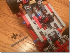
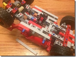
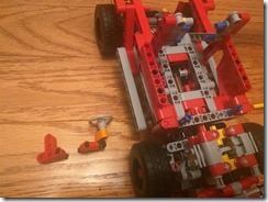
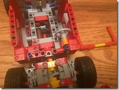
Motorizing the LEGO 8070 Supercar

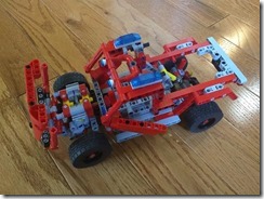
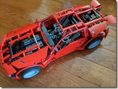
This particular model is not a recent model.  It was released in 2011 and comes with a battery box, a motor, and a gearbox to control several functions – rear spoiler, lifting the hood, and opening the left and right doors.

This caught my interest because as I look at the build, it felt like the designers intended this model to be motorized.  I ordered the set from an aftermarket sale, and proceeded to motorize the model with as few additional pieces as possible.

Similar to how I approach motorizing any LEGO Technic model, it is best to think about placement of the steering and drive motors during the middle of construction.  It will be at that time where you come up with an inventory of additional pieces needed to mount the motors.

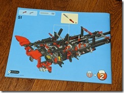
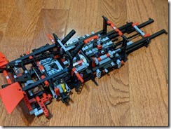
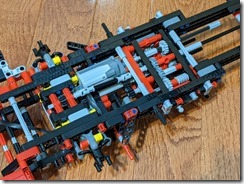
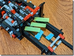
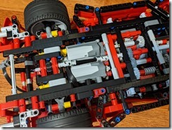
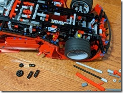
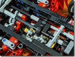
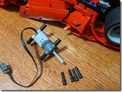
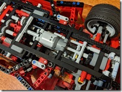
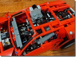
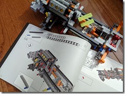
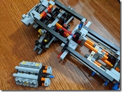
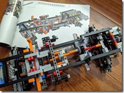
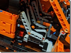
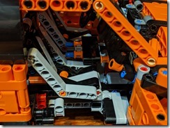
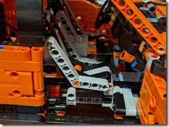
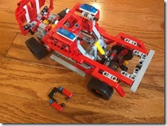
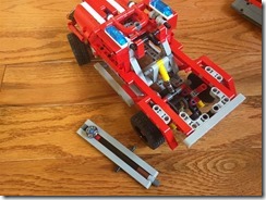
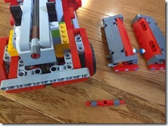
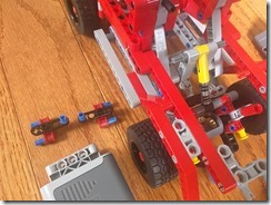
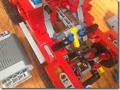
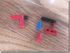
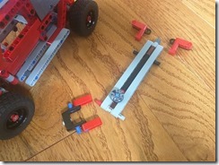
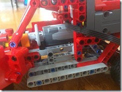
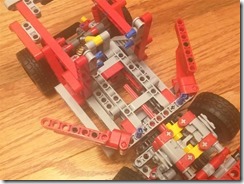
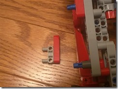
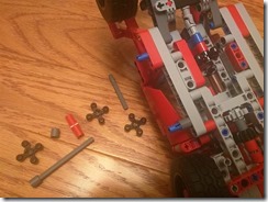
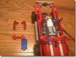
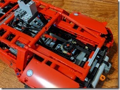
Here at Step 51 of the build, the motor that controls the functions is located at the right underside of the model.  An additional motor can be mounted in a similar way at the left underside.  Right at Step 51, there are five different axles extending towards the front and I’ve marked what function each one is connected to.

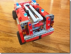
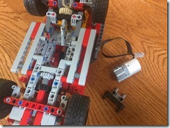
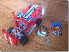
Lego8070-1 Lego8070-2 Lego8070-3 Lego8070-4

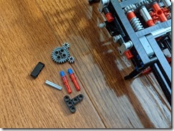
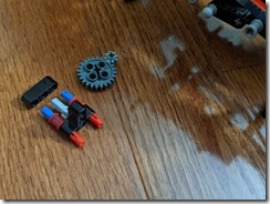
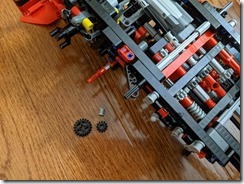
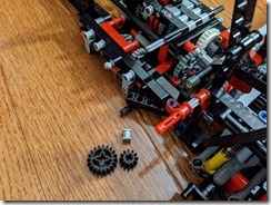
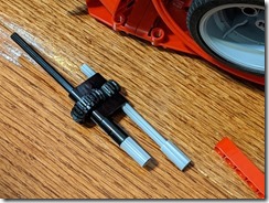
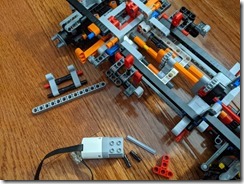
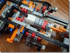
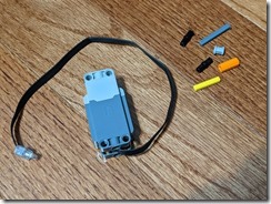
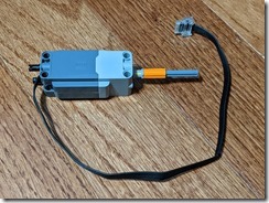
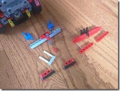
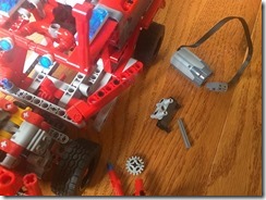
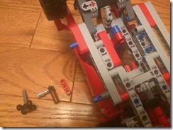
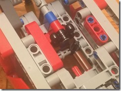
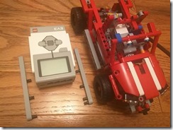
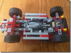
With three additional gears and a few pieces, I am able to mount an additional medium motor that serves as the drive motor.  The new gears join together as a gear train to replace the existing gear train at the left underside.

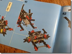
Step 51 is actually too far ahead and I had to backtrack to Step 41 where I am able to replace the gear train. That was probably the hardest part in installing the drive motor. After installation, the rest of the build is the same and straightforward.

Lego8070-5 Lego8070-6 Lego8070-7 Lego8070-8 Lego8070-9 Lego8070-10 Lego8070-11 Lego8070-12

With the memory of making a bad assumption when I motorized the LEGO Technic F-150 Raptor, I went ahead to finish the build to test out the drive motor, even before I had the steering motor in place.  A medium motor was too weak in the position where I placed it in the F-150 Raptor. I wanted to check if that is also the case with the 8070 Supercar.  Fortunately, the lighter weight of the Supercar checked out and the whole model can be driven with a medium motor.

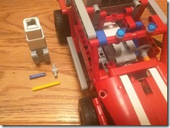
Looking at the underside of the model, one idea that occurred to me is to repurpose one of the axles controlling the power functions, and attach it to the axle that controls the steering, using a couple of gears.  Only a few additional pieces are needed, but it would mean sacrificing one of the power functions.  In this example, I repurposed the axle that lifts the hood.

Lego8070-12a Lego8070-12b Lego8070-12c

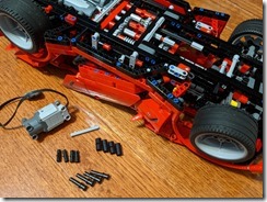
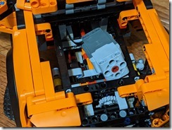
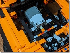
I eventually decided to keep the existing power functions, add a separate large motor, and a few more pieces to mount the large motor.  I chose the large motor here because there are way more mounting options with the large motor.

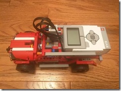
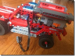
Disassembling the axle and the portion that controls the steering was just slightly difficult, but not impossible.  The motor cable is threaded into the cabin and up to the roof where I mounted the IR receiver for remote control.

Lego8070-13 Lego8070-14 Lego8070-15 Lego8070-16

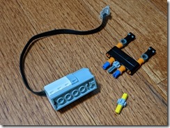
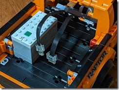
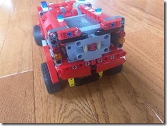
The IR receiver connects to the battery box located at the same place at the rear of the vehicle.  The steering and drive motors, in turn, are connected to the IR receiver.

Posted in Robotics | Tagged | Leave a comment

Motorizing the LEGO 42126 Ford F-150 Raptor

This LEGO Technic set came about 6 months ago.  Although I ordered it much earlier in the year, the 2021 shipping problems of FedEx caused a lot of shipments to be delayed by months.

This was one of the bigger LEGO Technic sets I’ve ordered.  I really wanted to find an easy way to motorize the set.  Like many of the Technic vehicles, I think the designers have always put the possibility of motorization into consideration with their designs.  With only a few additional pieces, and placing a control hub on the truck bed, it was not a difficult undertaking.  It did take me two attempts for a working solution.

As the set is being built, continuously think about where the motors would be inserted.  This allows for deciding what pieces will be excluded from the build, because those pieces may be harder to remove once the model is fully built.

From Step 106 of the build, I marked the axles that will be used for the engine motor and the steering motor. This is also where I opted to remove the V6 engine from the construct because I may be able to use that space to house one of the motors if necessary.  At the very least, I can re-use the pieces from the V6 engine.

Lego42126-1 Lego42126-2 Lego42126-3

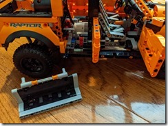
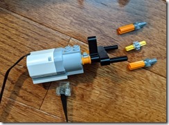
Then comes the part where I replaced pieces from the build with the engine motor.  Aside from the motor, I needed a couple of pins, a 3×3 T-beam, and a 5-LU axle from my external parts bin.  The 3×3 T-beam replaces the 3×1 orange beam to be used for mounting the motor.  The 5-LU axle replaces the 4-LU axle so the axle would extend into the motor.

I’m gonna mention early here that this next set of steps did not work out in the final build.  Follow along and you may realize earlier than I did on why they didn’t work out.  Here you can see the engine motor in my first attempt as it looked once the truck cabin has been completed.

Lego42126-4 Lego42126-5 Lego42126-6

With pieces that were excluded from the build, taken from the V6 engine and the hand-of-God steering, the steering motor could be positioned on top of the engine motor.

Lego42126-7 Lego42126-8

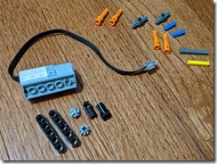
I eventually had to shuffle the pieces I used and ended up with the following set to mount the steering motor – six external pieces and the medium motor.  The steering motor is mounted on the same points under the truck dashboard where the V6 engine used to be mounted towards the front.

Lego42126-9 Lego42126-10 Lego42126-11 Lego42126-12 Lego42126-13

Things seemed to line up and I was ready to test it out.  I just loosely placed the hub on the truck bed, connected the engine and steering motors, and… big fail.

As it initially turned out, I was so used to using medium motors for motorizing my LEGO Technic builds.  Medium motors are small enough and very convenient to integrate into different locations in the model.  The Ford F-150 Raptor model was just big enough such that a medium motor was struggling to run the model because of its weight.  The steering mechanism was just fine with a medium motor, but the forward/reverse mechanism was not.

I knew then that I had to switch to using a large motor.  However, no matter how much time I spent looking at the space underneath the chassis where I initially placed the medium motor, I couldn’t find the space to put a large motor there.  I ended putting back the original pieces underneath the chassis.

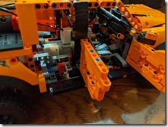
Another place where the forward/reverse mechanism can be driven is from the space where the V6 engine used to be located, under the hood.  Instead of the wheels driving the fake V6 engine, I placed a large motor there to drive the wheels, with no need for any additional external pieces, except those taken from the displaced V6 engine and the hand-of-God steering mechanism.

Lego42126-14 Lego42126-15 Lego42126-16 Lego42126-17

Lining up the cables underneath the cabin and out to the back of the truck, replacing the rear bench seat, we put a control hub on the truck bed and attach the cables.  The bed is spacious enough to use any of the several hubs that can be used to drive the motors.  I opted to just try it with an older Power Functions hub.

Lego42126-18

Using the mobile app to drive the truck was easy enough.  Select a good model that can use Port A for the engine motor and Port B for the steering motor.

Tagged | Leave a comment

Playing with Single Board Computers

2020 sent me working from home.  While not being able to physically meet with friends as often as I’d have wanted, I had some spare time to dig deeper into my Raspberry Pi equipment and other single-board computers (SBCs).

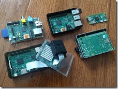
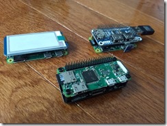
My stash included a couple of old Raspberry Pi Model B, a Pi2 Model B, a Pi3 Model B, and a Pi Zero.  Over the past few months, I’ve since purchased a bunch of additional Raspberry Pi equipment, including four Raspberry Pi4 boards and cases, several hats, and other single-board computers.

IMG_20200511_105123265     IMG_20200515_125203134

Over the course of 2020, I’ve installed several operating systems on them, including FreeBSD and the beta 64-bit Raspberry Pi OS.  I even ventured to re-attempt installing and making use of Windows IoT Core where I was not surprised to see that it was still a frustrating experience.  Looks to have been abandoned by Microsoft in favor of Windows 10 on ARM.

IMG_20200405_221506362     IMG_20200407_010501953     IMG_20200407_161051677     IMG_20200407_191420747

A few of my new purchases are worth noting.

Buy your microSD cards in bulk.  I think I ended up using more than a dozen 32GB cards for use in these tiny computers.  It’s not too bad to spare $10 for each SBC, for the convenience of not having to reuse and reformat the same card as I played around with each system.

The official Raspberry Pi keyboard is impressive.  It is compact, and also works as a USB hub.  Having additional USB ports is quite useful, particularly for the original Pi Zero which didn’t have built-in WiFi.  The Pi Zero W has built-in WiFi, which I ended up purchasing a couple of.  But with the Raspberry Pi keyboard, I could just plug-in an extra dongle for a cordless mouse and also use other nano adapters.  Dual-band 802.11ac WiFi adapters cost less than $20.

I incorrectly purchased the UK version of the keyboard.  That was my mistake, because I suffered several months accidentally hitting that backslash key that was placed beside the left Shift key and reduced the width of that left Shift key.  It was only last month that I gave in to frustration and purchased the US version.  I suppose you Brits use the right Shift key more often, and the small size of the left Shift key isn’t an irritation.

I remember using the Pi2 Model B for a Kodi (previously XBMC) media center about 10 years ago.  With the arrival of Chromecast, Roku, and Fire stick devices over the past few years, I don’t need the Pi as a media center anymore and can reuse it for other things.

I also tried to use them as a desktop computer, even if it’s just for using the web browser.  It is my opinion that only the Pi4 has enough processing power to provide a usable desktop experience.  The older models just don’t cut it, with too much lag in the user experience.

IMG_20200515_124454732     IMG_20200515_123937426_HDR

At least one Pi4 is up 24/7 on my network, serving as an internal Minecraft server, with occasional guest access from the outside.  The Pi4 is powerful enough and can have up to 8GB of memory, such that running Docker containers for isolated testing of some applications has not given me any issues.

Speaking of variations on the ad-hoc SBC standard of the Raspberry Pi, I searched for other ARM-based SBCs for comparison with the Pi models.  I ended up ordering a few of them, with the intent of cross-compiling other operating systems for the boards.

The first board I set up is a NanoPi NEO3.  I ordered the NanoPi NEO3 with the typical enclosure because I’ve planned to place this permanently on my network.  Its processor is equivalent to the ARM Cortex-A53 found on the RPi3, it’s got gigabit Ethernet, and it’s got a USB 3.0 port, all on a 48×48 mm form factor.  It runs the latest 64-bit UbuntuCore distribution and I use it to test VPN servers OpenVPN and WireGuard.  It performs my periodic DDNS registration and I could probably stick the Pi-hole service in there too.  It doesn’t have wireless connectivity, but which can be added through one of those tiny USB nano adapters.  It also doesn’t have any display ports, though I’m curious if the USB 3.0 port is enough to drive output to one of those DisplayLink USB monitors.

NanoPiNEO3-1

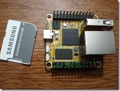
The next boards that I bought were a pair of RockPi S boards.  The combination of the low cost of these boards ($15 for a 512MB model) with the 64-bit A35-level processor (marketed as a low-power and high-efficient ARMv8 architecture compared to the A53 found on the RPi3) makes these tiny boards more powerful than a similar-sized Raspberry Pi Zero/W.  It has WiFi and Bluetooth 4.0 connectivity.  It also has an option of having up t0 1MB of NAND memory which you may be able to squeeze-in a tiny embedded Linux distribution if you don’t want to use a microSD card.  One gotcha I encountered on this board is that it doesn’t have a WiFi MAC address stored in hardware/firmware, so you have to define its WiFi MAC address through a boot configuration file.

RockPiSv13-4

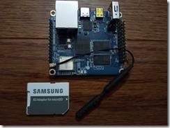
Another board that I bought was the OrangePi Zero2.  This board comes in a 53×60 mm form factor, but comparable in specs to the larger RPi3, also with built-in WiFi and Bluetooth 5.0 wireless connectivity.  Everything is open-source, with 64-bit Debian, Ubuntu, and Android distributions source available for download here.

OrangePiZero2-1

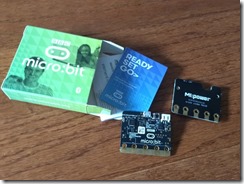
There were other purchases, some of which I have not even gotten to.  I bought a few Arduino boards and hats, some XBee connectivity modules, and some ESP32 modules.  One of the boards I’m very excited about is the BBC micro:bit.  I have both the v1 and v2 boards.  My excitement with the micro:bit is its appeal as a programming platform for younger kids who are thinking of pursuing a career in engineering, science, or technology.

IMG_20200523_173222875

Programming is on track to become a general-purpose skill that every profession would require.  I strongly believe that during the years around middle school, kids have so much enthusiasm and interest in learning, that it’s best to introduce them to programming at that time.  I hope to contribute driving this interest for these young learners.

Leave a comment

Motorizing the Lego Technic 42075 First Responder, Part 3

In Part 1 of the series, I used the EV3 brick and motors to motorize the Lego Technic 42075 retail set.  While very flexible in programming and remote controlling the vehicle, the EV3 brick takes up the whole truck bed because of its size.

In Part 2 of the series, I used the Power Functions brick and motors.  The smaller sizes of the brick and motors allowed me to retain the truck bed “side doors” and the spotlight attachment.  It also allowed both driver and passenger seats to be retained because the engine motor can be mounted underneath the vehicle, instead of taking up the passenger space.

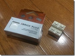
Using the Power Functions had its limitations.  Infrared is used to control the engine and steering motors, so line of sight is necessary when controlling it remotely.  Additionally, I felt there were too many extra Technic pieces needed to mount the Power Functions brick.  The infrared limitation can be overcome by using an sbrick receiver, an amazing 3rd-party product that communicates via Bluetooth, and can control up to four Power Functions motors.

SBrickPlus

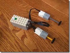
There are other pure-Lego options that are available.  One option is using the Power Functions 2.0 brick and motors.  The PF 2.0 brick is controlled via Bluetooth, and the motors are same in size to the Power Functions motors.  The brick and motors have to be purchased individually, unless you have the 60197 Passenger Train retail set or the 76112 Batmobile retail set.

LegoPowerFunctions2

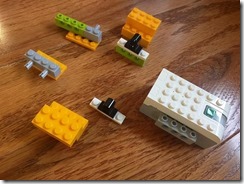
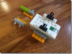
The Power Functions 2.0 motors are similar to the WeDo 2.0 motors, and the bricks are also similar; just additional mounting extensions on the WeDo 2.0 brick.  Since I have the WeDo 2.0 set, I opted to use mostly extra pieces from that set to motorize the 42075 First Responder.  There are a few additional Technic pieces I used to mount the motors, in the same way I mounted the Power Functions motors.

First step is again clearing off the cabin and truck bed space, in preparation for attaching the brick and motors.  From the re-used pieces, you can prepare the attachment of the spotlight and its beams.  Note again that I interchanged the 3LU-axle with the 5LU-axle because I need the 3LU-axle to attach the engine motor.  The spotlight and beams are offset upwards from the original position by 2LUs.

Lego42075-WeDo2-01 Lego42075-Wedo2-02 Lego42075-WeDo2-03

Although a little more compact, note that the Power Functions 2.0 or the WeDo 2.0 bricks are 4LUs in width so the construct for attaching the brick is asymmetrical (towards the left side of the truck).  Because of the smaller size of the brick, the rear of the truck can stay pretty much the same as the retail set build.

Lego42075-WeDo2-04 Lego42075-WeDo2-05 Lego42075-WeDo2-06 Lego42075-WeDo2-07

Finally, use a few extra Technic pieces to mount the engine motor underneath the vehicle, and the steering motor in the center of the cabin.

Lego42075-WeDo2-08 Lego42075-WeDo2-09

With the WeDo 2.0 brick and motors, you can use or write simple programs (Android program shown here) or use the WeDo 2.0 applications to control the engine and steering.

Posted in Robotics | Tagged , | Leave a comment

Motorizing the Lego Technic 42075 First Responder, Part 2

After my work of motorizing the Lego 42075 with an EV3 brick and EV3 motors, I searched and found similar work with motorizing the same retail set, but using the smaller brick and motors from Lego Power Functions; link here.

I have enough Lego pieces around the house to create a similar build.  And couple with my own goal of minimizing the set of needed extra pieces, trying to re-use as much of the pieces in the Lego 42075 retail set.  Because of the smaller brick and motors, the “side doors” on the truck bed can be retained and used to hide the brick.

First is designing a stable mount of the PF power brick unto the truck bed.  All the pieces shown here are extra pieces that are not part of the 42075 retail set.  Note that I also interchanged the out-of-the-box 3LU-axle (I’m using “LU” as the unit of measurement for the Lego pieces) with the out-of-the-box 5LU-axle, because I need the 3LU-axle to attach the engine motor.

Lego42075-PF-01 Lego42075-PF-02

Next would be to securely attach the rear end of the brick to the rear of the truck, while providing some anchor points for the truck bed side doors.  This is a mix of existing pieces and extra pieces, and builds the attachment all the way to the underside of the truck bed.

Lego42075-PF-03 Lego42075-PF-04

Next are the extra pieces to re-attach the beams that hold the spotlight accessory.  Because of the bulk of the brick taking up space on the truck bed, the spotlight and beams are shifted back by 2LUs and up by 2LUs; it is at least still functional.  Note the front attachment, re-used from existing pieces, that securely attaches to the front cabin to prevent wobbling on the spotlight and beams.

Lego42075-PF-05 Lego42075-PF-06

Then use some extra pieces to place the steering motor in the center of the cabin.

Lego42075-PF-07 Lego42075-PF-08

Finally use a similar set of extra pieces to attach the engine motor.  Thread the motor cable inside the vehicle frame before attaching it.  Because the Power Functions motors are shorter than the EV3 motors, there is enough space at the bottom of the vehicle to place the engine motor (in contrast to having the EV3 motor take the space on the passenger side of the cabin).

Lego42075-PF-09 Lego42075-PF-10 Lego42075-PF-11 Lego42075-PF-12

At the time of assembly, I could not find my Power Functions infrared receiver and remote control, so I was not able to thoroughly test this build.  There is a cavity behind the cabin to place the infrared receiver and attach it to the two motors and the Power Functions brick.  I did not pursue this build any further because of its limitations, and decided towards a different and better build – see Part 3 of this series.

Lego42075-PF-13

Posted in Robotics | Tagged , | Leave a comment

Motorizing the Lego Technic 42075 First Responder

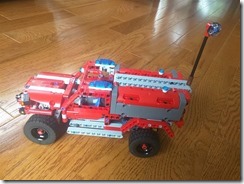
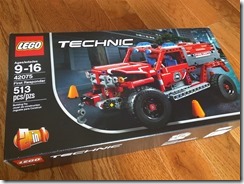
I’m finally getting around to writing about my experience in motorizing the Lego Technic 42075 First Responder.  This is a truck-like vehicle, similar in form to the Lego Technic 8081 Extreme Cruiser, but on a smaller scale.  I’ve previously put an EV3 brick and motors on the 8081 Extreme Cruiser documented here and here. When the smaller 42075 First Responder came out last year (2018), it looked like the space of the truck bed was just enough to put an EV3 brick, and I can surely find some space around the cabin to put the EV3 motors.

Lego42075-Box

One of my goals in motorizing the First Responder is to keep as short as possible the list of Lego pieces that are not part of the First Responder retail set.  Of course, the EV3 brick and two EV3 medium motors are necessary to provide the basic engine and steering control, but there were additional Lego pieces, such as extra gears, needed to completely attach the brick and motors.

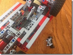
Motorizing the set with EV3 required a very minimal set of extra pieces.  There are only the four knob wheels which provide a 1:1 gear ratio with 90-degree directional changes, and an extra axle (shown later below to attach the engine motor).

From the retail build, remove the pieces comprising the canopy and truck bed; these pieces will be re-used in the following steps to attach the brick and motors.

Lego42075-EV3-01 Lego42075-EV3-02

Re-attach one of the gears that will be used for the steering mechanism.  Add the frame extension that will be the base for mounting the engine motor.

Lego42075-EV3-03 Lego42075-EV3-04

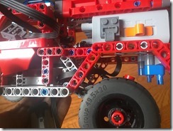
Turning the vehicle over, attach the first in the chain of knob wheels by using the extra axle. This attaches to the differential for the rear wheels that comes as part of the retail build.  Also continue building up the frame extension for the engine motor mount.

Lego42075-EV3-05 Lego42075-EV3-06 Lego42075-EV3-07

Complete the chain of knob wheels that ends up under the engine motor mount on the right side (passenger side) of the vehicle.

Lego42075-EV3-08 Lego42075-EV3-09 Lego42075-EV3-10 Lego42075-EV3-11

Rebuild the canopy with the steering motor in the middle interior of the vehicle, lined up to the gears that drive the steering mechanism.  The driver seat from the retail build can be retained.  Mount the EV3 brick upon the truck bed.

Lego42075-EV3-12 Lego42075-EV3-13 Lego42075-EV3-14 Lego42075-EV3-15

Finally, attach the engine motor vertically to the axle that jaunts up on the passenger side.  Additional pieces are used to secure both the steering motor and engine motor.

Lego42075-EV3-16 Lego42075-EV3-17 Lego42075-EV3-18

With the same nodejs program I used with the 8081 Extreme Cruiser for remotely controlling the EV3 brick through Bluetooth, I note that the chain of knob wheels provide a very stable gear train for running the EV3 motors. There is hardly any slippage on the gears.


Posted in Robotics | Tagged , | Leave a comment

Connecting a Parallel Printer to an Apple II (IIgs)

I almost gave up on this project.  It was a project meant to have been a jump-off point for a more ambitious one, but at the rate I end up working on these types of projects, I should probably scale back on my project list.

The Apple II Parallel Interface card (APIC), Apple Product 670-0021, caught my attention a few years ago. It is one of the interface cards that would allow you to connect standard parallel printers to your Apple II/IIgs. It stands out among other parallel interface cards because the cable attached to the card ends in a female DB-25 port instead of a standard 36-pin male Centronics port that connects directly to the printer. That DB-25 port opens up a lot of opportunities for connecting all kinds of peripherals.

Except that… in typical Apple style, the pinout for that DB-25 port, or the 26-pin ribbon connector in the APIC, is arranged in a very… uhm… eccentric way. From what I’ve searched, the only devices that offered this pin arrangement is the APIC and the Apple Lisa parallel port.

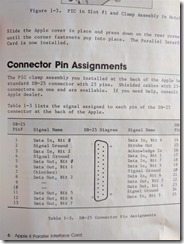
If you search for the typical DB-25 connector parallel port pinout offered in the IBM PC and compatibles, there is an almost one-to-one mapping to the 36-pin Centronics port of parallel printers. That DB-25 connector is the IEEE 1284 Type A standard as described here. At the very least, the data pins are in a contiguous arrangement. Pins 2-9 on both the DB-25 and the Centronics connector are the data pins. With the APIC, the following photo shows the arrangement as documented in the manual:

APIC DB-25 Pinout

That insane arrangement was enough for me to temporarily shelve my project for years. Then in 2013, David Schmenk used the APIC for a similar project. He probably wondered about that same peculiar DB-25 pin arrangement on the APIC, and went further to document the necessary mapping monstrosity to hook it up to a QuickCam camera.  I just wanted to hook the APIC up to a parallel printer.

Towards my goal, I dug up the only remaining parallel printer I have in storage. It’s an HP DeskJet 340, a portable printer that originally sold in the `90s for $300. I also had the standard DB-25 to Centronics cable that I used to connect the printer to old PCs.

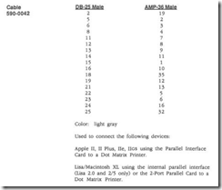
For those who want to connect the APIC to the parallel printer seamlessly, the standard DB-25 to Centronics cable is not suitable.  Instead, look for a cable that matches Apple Product 590-0042 which compensates for the APIC pin arrangement.  If you want to build your own cable, the mapping is documented in the Apple Peripheral Interface Guide:

AppleProduct-Cable-590-0042

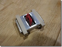
I took the challenge of building my own adapter, even though my soldering skills are way lower than that of David’s. When I paid a visit to Fry’s, I saw this useful RS-232 wiring adapter for adjusting the wiring connections of an RS-232 DB-25 cable:

RS-232 Wiring Adapter

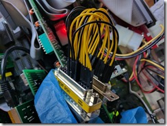
I started to re-map the pins, only to find out that the adapter does not allow re-mapping of Pin 1. In RS-232 connections, pin 1 is always connected to GND.  I really needed Pin 1 because that pin is used for the STROBE signal to the printer. I could have played around with some gender changers, but that would tie Pin 13 to GND which I might need for bidirectional data transfer (Pin 13 is the SELECT line for the parallel connection which is needed for Nibble mode data transfer). I gave up on the adapter, and proceeded with the following embarrassment:

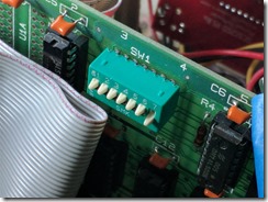
APIC Wiring  APIC DIP Switches 

APIC Pin # Name IEEE 1284 Pin #
2 Signal Ground 18
4 Signal Ground 19
5 Data Out, Bit 0 2
6 Data Out, Bit 1 3
8 Data Out, Bit 2 4
11 Data Out, Bit 5 7
12 Data Out, Bit 6 8
13 Data Out, Bit 7 9
15 Strobe Out 1
16 Acknowledge In 10
20 Signal Ground 20
22 Data Out, Bit 3 5
23 Data Out, Bit 4 6
24 Signal Ground 21

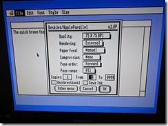
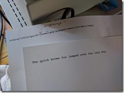
To test the cable, I installed the Harmonie DeskJet printer drivers, installed the GS/OS Teach application, and typed a short sentence. The printouts turned out well. There was an initial run (first sheet) that indicated one of the pins probably being disconnected and always getting a bit value of 1 on the lowest data pin — double checking and tightening the wiring fixed that problem.

Apple IIgs Harmonie  APIC Printouts

The follow-up project that I have in mind is to write software drivers that make use of the Nibble data transfer mode.  This would be similar to David Schmenk’s code for reading image data from the QuickCam camera.  It would make use of the BUSY, PAPER OUT, SELECT, and ERROR signal lines connected to four of the APIC Data In lines.  The data rate limit for Nibble mode is around 100kbps.  Ultimately, it may be enough to use the APIC as a cheap interface card for mass storage devices like the Iomega Zip Drive, whose block transfer protocol is widely documented in the Linux drivers repository (see the PPA3 driver here).

Posted in Retrocomputing | Tagged , , | Leave a comment

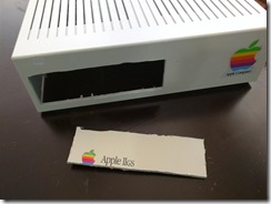
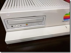
Apple IIgs Case Mod

Ever since a tiny little power adapter for the Apple IIgs was made available by James Littlejohn, I’ve always wanted to see what I can put into that cavernous space created by the absence of the old power supply.

The old Apple IIgs power supply takes roughly 1/5 of the internal space of the IIgs case.  In 2007, a tiny 2.5” x 2.5” power adapter called the LittlePower adapter was made available to allow a standard ATX power supply to be used.  I bought my LittlePower Adapter IIgs from ReactiveMicro at that time.  I think it’s now known as the LittlePower Flip and is sold at UltimateApple2.  Combined with the similarly tiny ATX Pico power supply from mini-box, it frees up a lot of space inside the case.

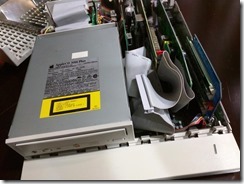
A plan for putting a standard 5 1/4” peripheral in there materialized and stayed in my workbench waiting to be allocated some time.  A recent long weekend gave me that time to grab some tools and start hacking at the case.

AppleIIgsCaseMod-2     AppleIIgsCaseMod-3

I’m not a professional case modder and it shows.  I was experimenting with the attachments on my rotary tool and the mistakes are evident in the top side of the hole.  This was more a proof-of-concept than anything else.

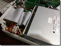
It now allowed me to use my Apple II High Speed SCSI Card to connect both an internal solid state drive (scsi2sd from Michael McMaster) and a SCSI CD-ROM device.  Remember to set the booting drive with a higher ID in the SCSI chain.

AppleIIgsCaseMod-1     AppleIIgsCaseMod-4

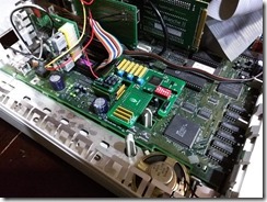
Internally, with the 5 1/4” device in there, you would lose the use of Slots 1 and 2.  I was able to squeeze the scsi2sd solid state drive towards the rear of the case, and the IDC cable runs underneath the device into the SCSI card on Slot 7.

AppleIIgsCaseMod-6     AppleIIgsCaseMod-7

I probably violated a dozen of best practices to electronically isolate components from each other.  I didn’t even use cardboard shielding between some cards in the slots.  So please, if you want to do this mod, do it right and take the necessary precautions.

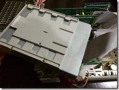
To keep the 5 1/4” device somewhat steady in place, I attached a mounting plate underneath the device.  These mounting plates are the same ones used for these devices in older Macintoshes, particularly the LC series.  You can still readily buy them as spare parts.  I drilled a couple of slits in the mounting plate with a rotary tool.  The slits are positioned in such a way to mate with the two plastic standoffs from the bottom of the case that were formerly used to keep the old power supply in place.

AppleIIgsCaseMod-8     AppleIIgsCaseMod-9

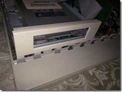
Using the CD-ROM was frankly just the proof-of-concept.  Since I rarely use a CD with my IIgs, it would be more appropriate to use an external SCSI CD-ROM device.  I will probably replace it with the SCSI floptical drive I used in an older post.  Or even with one of those SCSI-PCMCIA devices having the 3 1/2” form factor and having the PCMCIA/CF/SD slots in front for easy access.

UPDATE 11/8/2016:

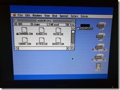
As originally planned, the SCSI CD-ROM will be rarely used.  Instead, I first tried with a SCSI floptical drive and was able to mount 1.44 MB MSDOS disks.  The GS/OS MSDOS FST driver only has read capability, so I can transfer files into, but not out from, my Apple IIgs.  The drive is also an MFM-encoding drive, and cannot read the GCR-encoding 800 KB disks used with the standard IIgs external disk drives.

AppleIIgsCaseMod2-1     AppleIIgsCaseMod2-2

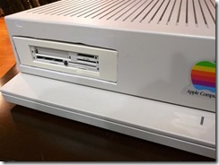
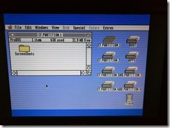
I suppose I could reformat a diskette as a 1.44 MB ProDos read/write block device, which should make it look like a very small-capacity hard disk.  However, I eventually settled for one of those SCSI-CF devices where I could use higher-capacity cards to transfer files in and out.  The SCM Microsystems PCD-50B provides multiple card readers in a 3.5” form factor.  With the standard adapter bracket and faceplate, it substituted into the 5.25” opening.  The only issue with this model is that the multiple card readers are addressed using multiple LUNs with a single SCSI ID.  I think the Apple II High Speed SCSI card firmware (or driver) only makes use of LUN #0, which is the PCMCIA slot.  In order to use CF or SD cards, I had to put them in one of those PCMCIA-CF-SD adapters.

AppleIIgsCaseMod2-3     AppleIIgsCaseMod2-4

Posted in Retrocomputing | Tagged , | 5 Comments

Remote Controlled EV3 Robot with Dual Gyro Sensors

I’m in the middle of another project involving the LEGO EV3 system.  My 11-year old has been making some inquiries about the gyro sensor that came with the EV3 Education kit.  To make the lesson more interesting, I wrote a simple EV3 project to illustrate the use of the gyro sensors, and as a bonus, also to illustrate the use of Bluetooth messaging.

The most common EV3 robot design we have used is the two-wheeled robot.  The two wheels are controlled by independent motors, and can therefore be used to move the robot forward/backward, as well as steer the robot left/right by varying the speed (and rotational direction) applied to the two motors.

The project is to remote control this kind of EV3 robot to move forward/backward and to steer left/right.  Instead of a joystick-like remote control, I want the controller to use gyro sensors, in the same way some smartphones use similar sensors to determine the phone orientation.  Such a controller can technically be attached to an arm, and the movement of the arm controls the robot, making it a hands-free experience.

A hands-free controller like this can accomodate three separate axis of rotations.  Some of you may be familiar with the concepts of pitch, roll, and yaw, such as those used in joysticks that control airplane movement.  For our EV3 robot to move forward/backward and left/right, we only need two axis of rotations.  I used pitch and roll in my simple controller design because those two concepts naturally fit the intended movements of the robot.

The controller is really very simple, with the two gyro sensors on port 2 and 3 of the EV3 brick, attached with a few hassenpins.

EV3-RemoteControlSender

The core part of the controller program merely measures, in degrees, the pitch and the roll of the controller and sends them out as Bluetooth messages to another EV3 brick.

image

The complete controller program has a few more steps added for robustness, debugging, and a mechanism to reset the gyro sensors because of accumulated errors caused by sensor drift.  It is still a relatively small program.

EV3-RemoteControlSender-Program

The receiving program in the EV3 robot is also simple.  The core part of the program receives the pitch and roll values, applies gain factors to both of them (to translate the pitch and roll degrees to values that can be applied to an EV3 move and steering block), and sets the parameters for the move and steering block that controls the robot wheels.

 image

The complete receiver program also just has a a few additional steps, mainly to limit the resulting values to fall within –100 to 100, which are the values that can be fed into the move steering block.

EV3-RemoteControlReceiver-Program

Here’s what a sample run of the two programs look like:

Posted in Robotics | Tagged , | Leave a comment