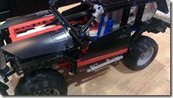
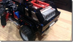
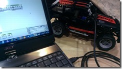
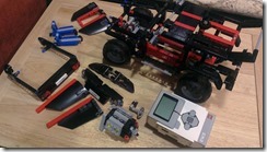
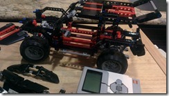
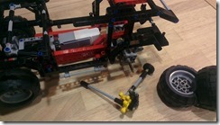
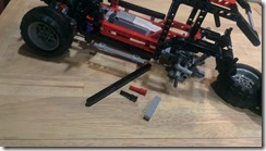
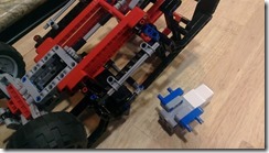
Remote Controlled EV3 Robot with Dual Gyro Sensors

I’m in the middle of another project involving the LEGO EV3 system.  My 11-year old has been making some inquiries about the gyro sensor that came with the EV3 Education kit.  To make the lesson more interesting, I wrote a simple EV3 project to illustrate the use of the gyro sensors, and as a bonus, also to illustrate the use of Bluetooth messaging.

The most common EV3 robot design we have used is the two-wheeled robot.  The two wheels are controlled by independent motors, and can therefore be used to move the robot forward/backward, as well as steer the robot left/right by varying the speed (and rotational direction) applied to the two motors.

The project is to remote control this kind of EV3 robot to move forward/backward and to steer left/right.  Instead of a joystick-like remote control, I want the controller to use gyro sensors, in the same way some smartphones use similar sensors to determine the phone orientation.  Such a controller can technically be attached to an arm, and the movement of the arm controls the robot, making it a hands-free experience.

A hands-free controller like this can accomodate three separate axis of rotations.  Some of you may be familiar with the concepts of pitch, roll, and yaw, such as those used in joysticks that control airplane movement.  For our EV3 robot to move forward/backward and left/right, we only need two axis of rotations.  I used pitch and roll in my simple controller design because those two concepts naturally fit the intended movements of the robot.

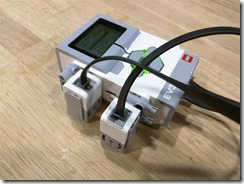
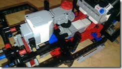
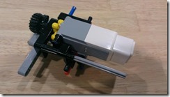
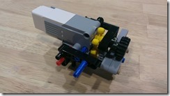
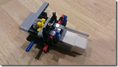
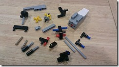
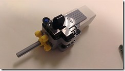
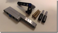
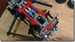
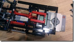
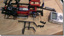
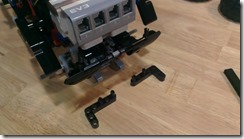
The controller is really very simple, with the two gyro sensors on port 2 and 3 of the EV3 brick, attached with a few hassenpins.

EV3-RemoteControlSender

The core part of the controller program merely measures, in degrees, the pitch and the roll of the controller and sends them out as Bluetooth messages to another EV3 brick.

image

The complete controller program has a few more steps added for robustness, debugging, and a mechanism to reset the gyro sensors because of accumulated errors caused by sensor drift.  It is still a relatively small program.

EV3-RemoteControlSender-Program

The receiving program in the EV3 robot is also simple.  The core part of the program receives the pitch and roll values, applies gain factors to both of them (to translate the pitch and roll degrees to values that can be applied to an EV3 move and steering block), and sets the parameters for the move and steering block that controls the robot wheels.

 image

The complete receiver program also just has a a few additional steps, mainly to limit the resulting values to fall within –100 to 100, which are the values that can be fed into the move steering block.

EV3-RemoteControlReceiver-Program

Here’s what a sample run of the two programs look like:

Posted in Robotics | Tagged , | Leave a comment

Putting an EV3 into a Lego Technic Cruiser, Part 2

Continuing from my previous post, I was ready to put in a second EV3 motor and drive train for the rear wheels of the cruiser.

The Mindstorms EV3 retail set comes with two large motors and one medium motor.  Conventionally, the two large motors are used to drive the wheels of an EV3 robot, using two-wheeled turning (where the wheels along the same axis are rotated in opposing directions to turn the robot left or right).  The medium motor is conventionally used for peripheral movements, such as moving a robot arm up and down.

Note that two-wheeled turning is not typically used in standard vehicles.  In a standard vehicle, the engine drives one axis, either front-wheel or rear-wheel driving, and the steering wheel is used to turn the front wheels left or right.  Most Lego Technic sets, aside from the robot sets, are patterned after a standard vehicle.

I’ve already put the EV3 medium motor as the steering motor for my modified cruiser.  Now I’m trying to find a position for an EV3 large motor to drive the gear that is exposed underneath the dashboard.  These are some of the positions I’ve explored:

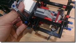
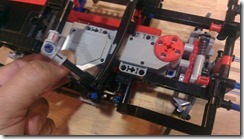
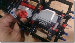
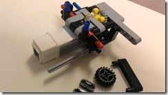
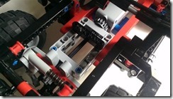
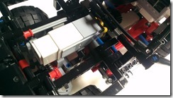
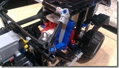
LegoCruiser-P2-1  LegoCruiser-P2-2  LegoCruiser-P2-3

That large motor sure takes up a lot of space.  The first two configurations put the motor axis at the front, under the hood, and I would need to have a gear train going backward to the gear under the dashboard.  However, the big part of the motor takes up a lot of space inside the cruiser cabin.

I really wanted to leave some space inside the cabin for future expansion, like a toy figure, a camera, or an Arduino.  So I initially settled for that third configuration, where the motor axis is inside the cabin and have a shorter gear train going towards the gear under the dashboard.  The big part of the motor does take up the whole front and precludes me from putting the hood back onto the cruiser. I also had to borrow a large gear from the EV3 set as part of the gear train.

LegoCruiser-P2-4

Even with that third configuration option properly set up, I felt that the 90-degree angle in the gear train was a weakness.  I tried spinning the motor axis manually to see how it runs, and the gears would often slip at that 90-degree angle.

I was in a bind.  None of the configurations seemed to work out.  Because I wanted the gear train to be stronger, the only other possible solution is to place the motor horizontally inside the cabin.  It would take up the whole cabin space, but the motor axis would fall directly above the gear under the dashboard and there would be no angles in the gear train.

I gave up for the day and noodled over it for a couple of weeks.  One day afterwards, I had a conversation with Claire about the difficulty I’m having with the modified cruiser.  I showed her the different configurations I’ve been trying with the motor and the unsuitability of each of those configurations.  After looking at it for a few seconds, she casually suggested, “Dad, just use another EV3 medium motor.”

o_O

I had been so caught up with trying to fit that EV3 large motor to drive the cruiser, that I never even thought of testing out a different piece.  The EV3 medium motor is not as powerful as the large motor, but after running some tests, we found that it was still enough to drive the cruiser.  Back last summer, when I purchased the EV3 set, I was so hooked into EV3 so that I also purchased additional pieces, additional sensors, and an additional medium motor.  I did have a second EV3 medium motor to use.

Going back to look at the engine space where I can place the second medium motor, I looked for mount points where I can attach the motor.  There is the gray frame at the bottom, there are the black horizontal beams running front to back on each side, and there are a couple of red connector pins at the front.

LegoCruiser-P2-5

One of my goals with this project was to “borrow” as few pieces as possible from other Lego sets.  If I can complete this by utilizing just the Lego Cruiser pieces, plus the EV3 brick and motors, then it would be easier for others to do the same.  I had some leftover pieces from the right angle gear train that I removed, some pieces from the passenger chair, some pieces from the V4 engine, and some pieces from the cruiser rear that I could reorganize.  With all those pieces, I came up with a construct that would rival that of a Star Wars vehicle.

LegoCruiser-P2-6  LegoCruiser-P2-7  LegoCruiser-P2-8

Since these are just leftover pieces, the construct is asymmetrical.  I think I also included too many mount points: four mounts to the bottom frame, two or three mounts to the horizontal beams, and an axle mount to one of the red connector pins.  It came out really stable, but I could have saved more pieces by reducing the number of places where I mounted the motor.  Assembling the construct is pictured as follows:

LegoCruiser-P3-1  LegoCruiser-P3-2  LegoCruiser-P3-3  LegoCruiser-P3-4  LegoCruiser-P3-5  LegoCruiser-P3-6  LegoCruiser-P3-7  LegoCruiser-P3-8  LegoCruiser-P3-9

Attaching this construct into the engine cavity of the cruiser is a little difficult.  It would have been easier to attach it while early in the process of building the cruiser frame.  The number of mount points I used also added a bit to the difficulty.

Once I got the motor in there, the rest is just attaching the decorative parts of the cruiser:  the steering wheel, the driver chair, the hood, the side doors, and the modified rear panel.  There was one beam and a few small pieces left, but I am surely glad I was able to rebuild the cruiser with its own set of pieces.

LegoCruiser-P4-1  LegoCruiser-P4-2  LegoCruiser-P4-3  LegoCruiser-P4-4  LegoCruiser-P4-5  LegoCruiser-P4-6

The drive motor is attached to Port C of the EV3 brick, and the steering motor is attached to Port D.  The USB port used to download a program to the brick is still accessible.  Using the Bluetooth connection is preferable since you don’t have to fiddle with wires nor need to run the program using the buttons on the EV3 brick.  Here’s a link to a video showing the autonomous cruiser running a short EV3 program:

https://www.youtube.com/watch?v=p-XC_OytYgE

In the test runs, I noticed that the 3-gear straight gear train that drives the rear wheels would occasionally slip.  I may have underestimated the weight that the EV3 brick puts on the cruiser and the increased torque requirements to move the cruiser forward.  I don’t think a stronger motor is needed, so I just lowered the speed of the motor to reduce the gear slippage.

Posted in Technology | Tagged , | Leave a comment

Putting an EV3 into a Lego Technic Cruiser

This is the first of few posts about my project in getting an EV3 brick into one of the Lego Technic retail sets.

I’ve always had a Lego Mindstorms robot kit ever since Lego came out with the NXT.  Though I’ve played with Lego bricks since I was a kid, it was only with the NXT that I became interested with these Technic sets.  And I was hooked.  I even purchased the older Mindstorms Robotics Invention System right after I got the Mindstorms NXT.

I have been following the Mindstorms EV3 since Lego announced and showed it at CES 2013.  After months of deciding between the education set and the retail set, I eventually bought the latter last summer (although I’m still keeping an eye for a good deal on the education set).

The EV3 was a radical evolution.  The memory capacity was greatly increased that you don’t have to worry about running out of space for the programs you download to the brick.  The now Linux-based system opens up a lot of possibilities.  Even the motors and sensors were significantly improved.

I’m always on the lookout for things where I can embed the EV3 brick, motors, and sensors.  This time I thought of looking into one of the existing Lego Technic sets.  My initial candidates were the Lego 8070 Supercar and the Lego 8081 Extreme Cruiser.  Both of them are retired sets, and there are other current sets that can possibly substitute, but the 8081 Extreme Cruiser attracted me because it really looks like it was made to be modified the way I was planning to.

I started out with assembling the cruiser, but excluding the parts that are purely decorative.  I call these excluded parts “fluff” because they are not part of the structural or functional aspects of the set.  As I expected, the V4 engine is purely fluff.  I was partly surprised that the steering wheel is fluff and not used to steer the front wheels.  I left alone the suspension system and the differential mechanism for the rear wheels.

LegoCruiser-1  LegoCruiser-2

The wheel/gear at the roof is used to manually steer the front wheels.  The next step is to replace this manual steering mechanism with an EV3 motor.  I removed the gear system with the 90-degree angle rotation and that left a cavity at the bottom almost enough to squeeze in the EV3 medium motor; I eventually had to remove one of the straight horizontal beams in order to snugly fit the motor.  I sacrificed the first of two front seats for the parts needed to attach the motor.  Note that it really helps if you temporarily detach the wheels while you’re working with the vehicle structure.

LegoCruiser-3  LegoCruiser-4  LegoCruiser-5  LegoCruiser-6

Next comes the part of finding the place to put the EV3 brick into.  It’s too bulky to put it in front in place of the V4 engine.  The rear part of the cruiser has a very nice enclosure where the EV3 brick can be inserted into.  I repositioned the couple of angled beams that block the full brick from being inserted.  With that, the brick can be inserted further and its weight is better supported by the vehicle structure.  It was even able to accommodate the brick with a rechargeable battery – the rechargeable battery option adds one unit of measure to the height of the brick.

LegoCruiser-7  LegoCruiser-8  LegoCruiser-9

At this point, the only major piece remaining to be attached is the EV3 motor that will drive the rear wheels.  The Extreme Cruiser set actually exposes the rear wheel drive with a single gear right underneath where the dashboard would be.  The set comes with nothing to turn that single gear, except maybe by reaching in with a finger.  The gear is actually just used to drive the decorative movement of the V4 engine.  However, it was strategically placed so that it can easily be driven by adding a gear train and a motor.

Positioning this gear train and second EV3 motor brought some complications.  More on that, and the solution suggested by my kid, on my next post.

Posted in Technology | Tagged , | Leave a comment

Getting the kid started with Lego Technic and Mindstorms

Last summer, I started to teach my kid about building with Lego Technic, particularly using the EV3 Mindstorms set.  Though she had been building with non-technic Lego bricks for years now, the Technic pieces involve a different mindset, dealing more with beams and pins rather than bricks and studs.

One of the original constructs from Claire is this dog head that we attached to a mini robot we built from one of the Lego books we have:

LegoEV3DogHead

The robot was from Yoshihito Isagawa’s Lego Mindstorms EV3 Idea Book, but the head was Claire’s original design.

Posted in Technology | Tagged , | Leave a comment

Creating an Apple IIgs GS/OS Live CD

The Apple II High-Speed SCSI card is one of my favorite peripheral cards for the Apple IIgs.  I typically install System 6.0.1 into a SCSI hard drive and use that as my boot and mass-storage drive.  Any old “SCSI” hard drive should work, but what I use is the scsi2sd adapter that allows me to emulate the SCSI drive with a microSD card.  It additionally allows me to make a raw backup of the drive contents using any disk imaging tool on a machine that has a slot for SD/microSD (I use the standard dd utility).  With CiderPress, I can even import files into the microSD card.  Files that I later read from within the GS/OS environment.

GS/OS can either boot from a drive containing a raw ProDos file system (maximum size is 65535 blocks, each block being 512 bytes, a little less than 32 MiB in total size) or, with the SCSI card, from a partitioned drive with a ProDos partition (the partition having the same size limits).  For a partitioned drive, it has to be using the Apple Partition Map (APM) style of partitioning, and not the more common MBR or GPT partitioning.  The APM partitioning style was standard with older Macs, those that were before Intel-based Macs came about.

If you treat the CD as a regular block device and lay out the blocks like that of a hard drive, partitioned with APM style partitioning, then GS/OS can be booted from that CD.  Of course, with just APM style partitioning, the CD will not have the ISO9660 file system and will not be natively mountable in systems that do not understand APM-partitioned block devices.  These types of GS/OS-bootable CDs were evident in some popular CDs distributed around that time.  Examples are the Golden Orchard CD and the early Developer CDs made by Apple (like the Phil and Dave’s Excellent CD).

Below are the steps I followed to create a GS/OS-bootable CD.  This is just one of many ways that it can be done; I was just trying to use the simplest, and free, method on a Windows machine.

Third-party utilities.

If you haven’t done so already, download CiderPress.  This used to cost a few dollars, but Andy McFadden has since made it free and open-source.  This utility will let you work with ProDos and HFS file systems, with either raw file systems or an APM-style partitioned drive, and with either a real block device or an image of a block device.

Another utility I used is a drive image overlay/extraction utility.  There is either the Windows port of dd, or the Windows port of busybox (that includes dd as one of the commands).

Another utility I used is a Windows port of mkisofs.  I used this to initially create the APM partition map.  There are other options available to do this, including 1) using pdisk on an OS X machine, 2) using the commercial TransMac software, 3) using a combination of VirtualBox and GParted, or 4) waiting for Andy to include this feature in CiderPress (I saw that it is one of the requested features).

Finally, a hex/binary editor is always useful.  I use HxD because it’s simple and free.

Creating the bootable ProDos file system.

GS/OS needs to be installed into a ProDos file system somehow.  CiderPress easily lets you create an empty 32 MiB ProDos disk image – you then assign the disk image in an Apple IIgs emulator like KEGS/gsport and follow the standard GS/OS hard drive installation process.  Or you could download some pre-built bootable 32 MiB ProDos disk images around the net.  Check out Alex Lee’s What Is The Apple IIGS site.  I will use a ProDos file system image (e.g., P1_BOOT.PO) as the first, and sometimes only, partition in my APM-style partitioned disk image.

Creating the partitioned disk image.

I create a folder containing my file system images (e.g., P1_BOOT.PO, P2_APPS.PO, P3_HFS.PO, etc.) and run mkisofs:

mkisofs.exe -hfs -part -no-desktop -o CD.iso C:\FileSystemImagesFolder

This creates a hybrid ISO9660/HFS CD.  A hybrid CD is one where the CD files can be accessed using both the ISO9660 file system and the HFS file system, with only a single copy of the file data somewhere on the CD.  The files here, of course, are the file system images P1_BOOT.PO, P2_APPS.PO, and P3_HFS.PO; not the individual files within the the file system images.

If you plan to put more than one file system image in the CD, my example makes use of 32 MiB (65535 blocks) file system images so that using the hex/binary editor to modify the partition map will later be easier.

The partition map that mkisofs creates contains two entries only – an entry for the partition map itself, and another for the hybrid HFS file system.  The partition map starts at offset 512 (0x200) of the disc image and each entry is 512 bytes in length.

image  image

Replacing the partition map entries.

If I only had one file system image to put on the CD (e.g., P1_BOOT.PO), then that file system image will be positioned at offset 0xC000 (block 0x60) of the CD image.  We can replace the second partition map entry with the following pre-made 512-byte file:

image

busybox.exe dd bs=1 count=512 if=PRODOS1_65535.PME of=CD.iso seek=1024 conv=notrunc

What ends up is that we keep the CD ISO9660 file system, but we replace the hybrid HFS file system entry in the partition map with the ProDos partition map entry.

If I wanted to put more than one file system image on the CD, I need to enumerate the partition map entries at 512-byte intervals, then I need to edit each partition map entry to reflect the number of partitions and the offset of each partition in the CD.

For example, suppose I also wanted to make the second P2_APPS.PO (65535 blocks) and P3_HFS.PO (65535 blocks) file systems visible in GS/OS:

busybox.exe dd bs=1 count=512 if=PRODOS1_65535.PME of=CD.iso seek=1536 conv=notrunc

busybox.exe dd bs=1 count=512 if=HFS_65535.PME of=CD.iso seek=2048 conv=notrunc

Then edit the disc image to specify the correct count and location of the file system images:

image  image

image  image

Burn the CD image.

The final step is to burn the CD image into a real CD-R.  On Windows, I use ISO Recorder, but any raw-disc-image burning application should work.  For such a small CD image, I sometimes use the smaller 185 MB pocket-sized CD-R discs.  If you have the scsi2sd or other mass-storage devices (e.g., MO drive, SCSI-IDE bridge), you can actually dump the same CD image into those devices.

IMAG1469

Boot the CD from a SCSI CD-ROM drive.

Put the CD into a SCSI CD-ROM drive, attach the drive to the SCSI chain, and boot from the CD.  Remember that the Apple IIgs boots off from the SCSI device with the highest SCSI device ID, and that an unmodified Apple High-Speed SCSI card does not provide termination power to the SCSI bus.  Either mod the card or have another device provide termination power.

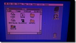
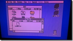
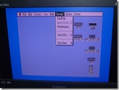
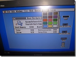
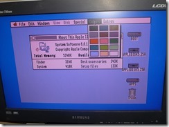
Here are some screenshots of one of my Apple IIgs booted from a CD with two file system images (the bootable ProDos file system image and one additional HFS file system image).  Note the block devices are locked/readonly.

IMAG1524  IMAG1525

Caveat with all the above – it should be obvious that because this is a CD, the drive is read-only.  Applications that attempt to write data back to the drive may or may not fail, but will surely lose that data because it is not persisted.

Files.

Posted in Retrocomputing | Tagged | 1 Comment

Explorations with Low-Powered Devices for the Apple IIe/IIgs

I recently posted my experiences with using a Bluetooth module to perform wireless ADTPro transfers with my Apple IIe.  At that time, I was powering the Bluetooth module from an AC adapter.

Seeing that the Bluetooth module power adapter was a standard +5v USB power adapter, I suggested a simple Apple II  peripheral card with a USB female port to provide the +5v power needed by these modules or devices.  +5v is readily available from pin 25 on the slot connectors (maximum of 500mA for all peripheral cards according to documentation).  A few minutes with the soldering iron came up with this contraption:

AppleII-USB-5v-1 AppleII-USB-5v-2

It surely was a product of an amateur, but it was enough for a proof-of-concept so that I could put the Bluetooth module inside the Apple IIe without an additional power line coming out of the case.  And with that, I was again performing wireless ADTPro transfers from my laptop using Bluetooth.

AppleII-USB-5v-SerialBluetooth

One thing to note about this Bluetooth module is that the serial port speed is set to 9600 baud by default.  The recent versions of ADTPro have removed support for 9600 baud.  You’ll have to follow the instructions for the Bluetooth module to configure it to start up at 115k baud.  115k is faster anyway, and the serial transfer speed is still slower than the Bluetooth transfer speed (meaning that it’s still the serial segment that’s the slower part of an end-to-end transfer).

Moving to the IIgs, I pulled out from my stash of devices a tiny Wi-Fi bridge IOGear GWU627.  This acts as a standard Wi-Fi bridge (802.11b, 802.11g, or 802.11n), except that it is very tiny and can be powered by a standard USB power adapter.  I put an Uthernet card in slot 2, my homemade USB peripheral card in slot 3, and wired them altogether with the GWU627 bridge also inside the IIgs case.

IOGEAR-GWU627-1 AppleII-USB-5v-Uthernet-1

With a standard Marinetti installation, my IIgs is now wirelessly connected to my home network.  DHCP works over the wireless bridge, and the IIgs receives an IP address from the home router.  The Marinetti applications Casper web server and Telnet client work as they should.  This could be a good way to run a 24×7 web server from your IIgs and make it available to the Internet – of course, only with the proper port-forwarding rules in your home router and only if your ISP allows hosting a web server and does not block port 80 incoming to your network.

AppleII-USB-5v-Uthernet-2 AppleII-USB-5v-Uthernet-3

Posted in Retrocomputing | Tagged | Leave a comment

Adding Wireless (Bluetooth) Support in ADTPro

It’s been months since I planned to look into adding Bluetooth support in David Schmidt’s fabulous ADTPro software.  I’ve been using ADTPro for years to transfer disk images for use in my Apple IIe using the Apple II Super Serial Card.  Over the years, it has garnered many additional features, such as providing a virtual drive over the wires.

My Windows (8.1 x64) laptop does not have a built-in RS-232 serial port, so I normally use a cheap (~$15) USB-serial cable. One that works for my laptop, because of its Prolific PL-2303 chipset, is the Startech ICUSB232DB25.  Coupled with a null modem adapter, I can use ADTPro to its maximum 115kbps transfer speed.

A few months ago, I wanted to see if I could do away with the physical serial cable.  This was about 20 months ago (I checked on when I ordered the Bluetooth-Serial board and saw an invoice for August 2012).  These Bluetooth-Serial boards come around to each cost about $20.  It’s probably cheaper if you’re willing to just get the Bluetooth-Serial module and wire them directly to the SSC data and power connectors.  However, this was just a proof-of-concept, so my setup looked like the following:

SuperSerialCardII BolutekBlutetoothModule

The Bluetooth-Serial board uses the Bolutek BLK-MD-BC04-B module (pictured on the lower right of the board).  It attaches to the SSC with a straight-through DB9-DB25 adapter, and uses the USB cable for the standard 5v power source.

Alas, at that time, my tests showed that although I can get wireless remote access to the Apple IIe, ADTPro did not fare as well.  Remote access is through Apple’s PR#2 and IN#2 commands and through Windows’ HyperTerminal program.  Everything seems to work properly on the Apple IIe end, but ADTPro’s use of COM ports exposed by the Bluetooth serial SPP services did not work for me (actually, it’s the rxtx library’s use of the COM ports – ADTPro just uses rxtx for serial port support).

I hatched a plan to update ADTPro to accommodate this.  After more than a year of getting de-prioritized, it finally got its due attention.  Starting a few days ago, I’ve finally got something like an alpha version of Bluetooth support working in ADTPro, tested only in Windows.

On the Windows end, any Bluetooth-enabled machine should work using the standard Windows Bluetooth drivers.  WIDCOMM-based Bluetooth controllers should also work.  I first had to pair my laptop with the Bolutek module.  Pairing is straightforward.  Having the Bolutek module in its regular slave-mode setting, it appears when I search for additional Bluetooth devices in my laptop, and the default pairing code is 1-2-3-4.  Once paired, you’ll see that it provides the standard Bluetooth Serial Port Profile (SPP) and creates the virtual COM ports (COM17 and COM18 in my setup).

ADTProBluetooth-1

ADTProBluetooth-2 ADTProBluetooth-3

I put on my software developer hat, and dived into the ADTPro source code within the Eclipse IDE.  David has really gotten the components cleanly modularized, and I only had to create a few classes to add the Bluetooth support.  Once built, Bluetooth is just an additional transport in the ADTPro runtime environment.

ADTProBluetooth-4 ADTProBluetooth-5

The Bluetooth connection is made directly to the SPP service, and not through the virtual COM ports.  Once connected, the standard serial port client on the Apple IIe can send and receive disk images wirelessly over Bluetooth.

ADTProBluetooth-6

It was enough for a proof-of-concept, and I’ll check with David on merging this upstream to ADTPro.  As with any proof-of-concept code, there’s some cleanup work to do.  Like displaying the friendly names, instead of the addresses, of the Bluetooth devices.

Also, on the Apple IIe end, I could probably splice the power wire for the Bluetooth-Serial board and get the +5v directly from the Apple IIe motherboard.  With the inexpensive prototype boards selling around the net, I am also thinking of a generic USB power source slot card like this:

AppleUSBPowerProject

It’s probably just a two-wire setup.  I’m just not motivated enough to look for my soldering iron buried somewhere in the garage for the moment.  If anyone (Bradley?) wants to mass market such a board, I’m one of your potential buyers.

Update 5/16/2014:

I tried my ADTPro build on another machine.  This time, I first tried using the virtual COM ports using the ADTPro Serial transport, and SURPRISINGLY, it works.  There may have been some changes in the rxtx library since 20 months ago, but I remember not getting it to work back then.

The serial port enumeration takes a while with these virtual COM ports, and it might seem like ADTPro is hanging, but just patiently wait for the dialog box to eventually come up, connect to the outgoing virtual COM port, and ADTPro works as it should.  Note that the baud rate you want to set on the ADTPro client is the baud rate of the communication from the Apple IIe to the Bluetooth board, not the baud rate from ADTPro to the virtual COM port.

So there. With other, maybe most, Windows machines or the proper Bluetooth stack, ADTPro correctly works using the rxtx library over the virtual COM ports exposed by the Bluetooth connection.  There’s no need for my ADTPro modifications (which I’ll just use in a separate follow-up project).

Posted in Retrocomputing | Tagged , , | 4 Comments

Updating my cable setup with the Raspberry Pi

I’ve delayed looking into the Raspberry Pi for quite some time now.  I’ve known how awesome it is, but also know that I didn’t have a lot of time to tinker around with it.  However, recent developments in late 2013 convinced me that I needed to spend time with this tiny computer.  Since the past holiday season up to today, I have bought two Raspberry Pis, each with an enclosure, all the nifty tiny USB hardware that extends its functionality, and even a real-time-clock extension attaching to the GPIO pins.

The things that convinced me to look into it are the developments related to cable TV (i.e., Comcast, Time Warner, FIOS).  There’s this cable tuner, called HD Homerun Prime, that you can purchase through the retail market.  Like TiVo devices, it takes in a CableCARD and attaches to your home router.  Cable providers are required by law to allow you to request a CableCARD if you have a subscription with them.  It’s normally free for one CableCARD, or sometimes they charge a minimal fee for it like $1/month.

With this CableCARD and the HD Homerun Prime, your cable tuners (3 in the HD Homerun Prime) are made available to your home network through DLNA/UPnP.  HD Homerun Prime had this UPnP capability made available in its firmware in late 2013.

We have a room in our house that doesn’t have a cable outlet.  Coincidentally, we have a combo TV/DVD there.  The only way we could get cable into that TV was by using a low-tech A/V sender/receiver that uses some RF frequency – the one that is highly susceptible to microwave signals (that is, the A/V signal craps out when the microwave is in use).

In 2013, the media center usage for Raspberry Pi took a dramatic upturn.  First, they made available a per-unit license for MPEG2 decoding for a low price of £2 (about $4).  A lot of cable providers encode their streams as MPEG2 (whilst I think most dish providers use MPEG4).  Another development was that they enabled CEC capability in the HDMI socket on the Raspberry Pi.  With that, the media center distributions for Raspberry Pi, like RaspBMC and OpenElec, provided all that I needed to switch over to a full UPnP solution to my isolated TV.

I installed the OpenElec distribution image.  It’s smaller and customized for a lean media center so a lot of software packages are not present.  But that’s why I bought another Pi just for general-purpose tinkering and relegated the first Pi for my isolated TV.  OpenElec can easily fit in an SD card with a small capacity.  I used a 2GB SD card.  I attached a nano-sized WiFi USB dongle (150Mbps), temporarily attached a USB keyboard/mouse, and connected the HDMI port to our main TV for testing.

OpenElec boots directly into XBMC.  There are several XBMC skins out there to customize its appearance, but I just stuck with the standard out-of-the-box skin “Confluence”.  First thing I noticed is that the HD Homerun Prime is detected as a UPnP source.  So I added the Favorites subfolder as an XBMC video source.  I’ve pre-selected the channels that would appear in the HD Homerun Prime Favorites subfolder through the small web interface exposed by the HD Homerun Prime, the same web interface where you can read the codes off when you set it up with your cable provider over the phone with their tech support.  I set up the Favorites so I could see a list of channels shorter than the full list of channels available to me.  Who watches those home shopping channels anyway?

The Raspberry Pi feature that caught me by surprise is the CEC capability.  With CEC, I actually didn’t even need a temporary USB/mouse keyboard to set up OpenElec. The cursor movement buttons on most modern TV remotes are received by the TV infrared receiver, and passed through the HDMI cable using this CEC feature.  The other device at the end of the HDMI cable, which is the Raspberry Pi, receives the cursor movement and uses that to navigate the XBMC interface.

One hiccup was that when I moved over the setup to the isolated TV, I found that my small TV/DVD device didn’t have the CEC feature.  It was a no-brand small 22” LCD TV, and from what I’ve read, some older smaller TVs do not have CEC.  So what’s available as a remote control for OpenElec/XBMC?  I didn’t want a full keyboard/mouse because it felt too geeky.

First, I tried Bluetooth and it worked.  I had a tiny Bluetooth USB dongle which the Pi readily recognized.  From OpenElec’s Bluetooth setting, I was able to pair an extra Wiimote controller that we have.  I tried pairing a no-name Wiimote clone, but it would only recognize the four cursor keys.  With an original Nintendo Wiimote, it was able to recognize the cursor keys, Enter and Cancel keys, and even the volume keys.  So that would have worked, but using a Wiimote still felt geeky.

I read that certain inexpensive RF remote controls (the ATI All-in-wonder remotes) would work, and it won’t cost more than $15;  I also read that most media center IR remotes would work and are actually less expensive.  In the end, I decided I want to use the existing remote control from that no-brand TV.  I ended up buying Flirc, sort of a universal learning IR receiver.  The Raspberry Pi easily recognized the Flirc dongle, and I was able to program/teach the dongle with the TV remove using the Windows application available from their site.  Very easily too.  I had to pick a remote button that the TV would not recognize.  I picked the “Guide” button and had it mapped to sending a “Ctrl-Home” keyboard equivalent to the Raspberry Pi.  In the Raspberry Pi XBMC layout (I had to use SSH or the command-line to do this), I added a mapping in the keyboard layout to make Ctrl-Home bring up the mapped HD Homerun Prime Favorites source.  What this accomplished was that the “Guide” button on the remote served as a go-back-to-the-top-level-menu command, then with the arrow keys in the remote, you can scroll through and select from your favorite channels.

With the UPnP streaming, I could even access my cable (each of the 3 tuners will be reserved as it is accessed) channels through UPnP players on any of our phones, tablets, or computers.  For Windows, you can easily see the HD Homerun Prime as a UPnP device and browse through the Favorites folder (it plays the cable channel in Media Player).  For Android devices, I use the combination of Skifta and WonderPlayer.

I opted to use the SD channels because it was using the wireless network.  I heard that HD channels, although possible, could put a strain in your wireless network.  Streaming HD channels to the Pi should not be an issue over a wired network though.  Also, I’ve yet to set up a new 802.11ac router to see if it provides enough bandwidth to switch over to using HD for my setup.

I’m now ready to return my cable box to my cable provider, and save on that $10-something they charge me monthly for it.  I will miss the DVR capability right now (also an additional $10-something per month that they charge), but also had set up a small Windows media center box to be my DVR.  I’ve yet to see if I can configure Windows and/or the motherboard to allow the media center to sleep/wake on-demand without the need to use some Wake-On-Lan software to explicitly wake it up.  I’ve tested it with WOL, but I really want it to automatically wake when something else in the home network makes a request to any of its services.  Having that media center setup also means that I could make it host the electronic program guide that can be accessed by my isolated TV.  But that media center setup is another story.

If only the HD Homerun Prime had an additional HDMI socket to directly connect one of the TVs that sit close to it.  But I’m not complaining.

Posted in Around the House | Leave a comment

Video options for the Apple IIgs

I’ve always abhorred CRT monitors.  They’re bulky, heavy, and they probably emit too much radiation to tire your eyes too quickly.  I’m so thankful that the computer industry, and every other video-related industry has switched over to using LCDs.

Retrocomputing is a hobby of mine.  The Apple IIgs is what I use the most from my collection of vintage computers.  The Apple IIgs made use of an RGB monitor through a DB-15 connector at the back of the computer.  A few years ago, Roger Johnstone provided the schematics to an RGB-SCART cable.  With some LCD monitors having a SCART input, this allowed me to finally get rid of my RGB monitor.  I use a Samsung 730MW monitor and that provides a very clear output from my Apple IIgs.

These LCD monitors with SCART input could start getting harder to find in the upcoming years.  I wanted to look at alternatives to displaying my Apple IIgs output on modern monitors.  It’s been an often-discussed topic in the vintage computer forums.  Ideally, we’d like to be able to use VGA, DVI, or even HDMI-capable monitors (composite-based output would be insufficient for me). For several years, Roger’s SCART cable was the only inexpensive way to do this.  There was a more expensive XRGB/XRGB2 converter that provided good output quality, but that turns out to be more expensive than your standard Apple IIgs investment.

As recent as last year, Nishida Radio from Japan offered an RGB-Component converter.  I recently purchased the converter from him and got a chance to test it over the holidays.  Although I wouldn’t call the output equivalent to that on the SCART cable, it’s pretty darn close.  Look for yourself in the following photos I’ve taken.  My monitor has both a SCART connector and a Component-In connector.

P1040235P1040238

P1040245P1040239

The ones on the left use the SCART cable and the ones on the right use Nishida’s RGB-Component adapter.

Nishida also has some other components for use with vintage computers.  My other purchases include the UNISDISK which emulates a Unidisk drive (attaches to the DB-19 drive connector at the back of the Apple IIgs), and a VGA adapter for the Apple IIc.  See all his stuff here.

Posted in Retrocomputing | 4 Comments

Out-of-band Authorization

A lot of applications require the need for an in-session authorization mechanism. This means that when an end-user is within an authenticated session, the end-user will be prompted to enter a set of credentials before he can be allowed to perform specific transactions. These transactions are identified as high-risk transactions, such as changing a password or changing a registered e-mail address. The set of requested credentials could be the same set used to sign-in to the application (which is confusingly often mislabeled as re-authentication), or it could be a different set of credentials specific for the transaction that is being requested.

Almost all the time, this in-session authorization mechanism is desired to be delivered or performed out-of-band. That is, the secondary credentials are either sent out to a delivery channel different from where the transaction was initiated, or the secondary credentials are entered in a delivery channel different from where the transaction was initiated.

I’m specifically addressing the general concept of authorization, instead of the more specific concept of authentication. In the context of using an out-of-band mechanism for authorization, if we identify that high-risk transaction to be the “signing-in” transaction, then the mechanism leads to what is known in the industry as multi-factor authentication.

Multi-factor authentication (MFA) is available in a lot of applications. However, being a specialization of the more general concept of out-of-band authorization (OOBA), there are scenarios that MFA do not take into account during application design. These scenarios, if not accounted for, often lead to an insecure implementation of a general OOBA mechanism.

High-risk Transaction Identification

The first step in an OOBA mechanism is to identify if a transaction is a high-risk transaction. Most of the time, just the transaction name itself is enough to identify it as high-risk. An example is the password change transaction.

There are times where identification depends on the payload of the transaction request. An example would be an ATM withdrawal where withdrawing less than a certain threshold is not considered high-risk, and withdrawing above that threshold is considered high-risk. In this case, the transaction request has to be inspected to determine whether it is high-risk or not. This has implications on application design because the application cannot prompt for secondary credentials before the user has even entered the transaction request details.

Transaction and Authorization Context

An important part of OOBA is the association of the authorization context with that of the transaction context. Before a transaction is allowed to go through, the authorization context associated with the transaction should be verified. It is not enough to verify just any authorization context; it has to be the authorization context associated with the transaction.

If the authorization context is verified in a separate operation than that of the transaction, it is very important that the context association be maintained. That is, it is not enough to ask a verification service, “Are these the correct credentials?” We have to ask the verification service, “Are these the correct credentials for this particular transaction request?”

In a web application, in order for the context association to be maintained, the transaction request and the secondary credentials should be sent in a single HTTP request. Technically, separate HTTP requests could be used, but would require a mechanism of associating the separate HTTP requests with each other.

Design Notes

Web Forms

Out-of-band authorization can be implemented in web forms through a user control embedded in the form. The OOBA user control visibility can be toggled depending on the position of a transaction within a workflow. For the most common type of OOBA, the user control merely provides entry fields where OOBA secondary credentials are entered.

Server-side validation of the transaction request and the OOBA credentials occur within a single HTTP request before the transaction is completed.

authzValidationNeeded = … depending on the transaction request payload …
if (authzValidationNeeded)
    authzCredentials = … retrieved from form fields …
    if Empty(authzCrendentials) || !Validate(authzCredentials)
    then
        return an authz error,
        allow the user to re-enter credentials,
        and resubmit transaction and credentials

Because of the importance of associating the authorization context with the transaction, the authorization context should not be validated in a separate earlier step (in a separate earlier HTTP request) than that of the transaction itself.

MVC Forms

The authorization token follows the same mechanism used in the built-in MVC AntiForgery mechanism; passed to the server as a separate form field. It differs only in that the token value is not generated at the time the view is generated. The token value is requested from the user by making the form field visible and having the user input the value.

Server-side validation of the transaction request is the same as that in Web Forms.

WCF Ajax Services

WCF Ajax services pose an implementation challenge because in a general architectural design, we want to separate the concerns of authorization with that of the transaction. If we require the transaction interface to be modified to accommodate the authorization credentials, like:

FooResponse FooOperation(FooRequest request, AuthorizationCredentials credentials)

Then authorization concerns interfere with the clean operation interface of the transaction.

Since it is desired to pass the authorization credentials in the same HTTP request as that of the transaction, the only other place we can pass them are through the HTTP headers.

Server-side validation of the transaction request and the OOBA credentials occur within a single HTTP request before the transaction is completed.

authzValidationNeeded = … depending on the transaction request payload …
if (authzValidationNeeded)
    authzCredentials = … retrieved from HTTP header …
    if Empty(authzCrendentials) || !Validate(authzCredentials)
    then
        return an authz error,
        allow the user to re-enter credentials,
        and resubmit transaction and credentials

On the client side, the transaction invocation is conventionally done through JavaScript. The invocation would originally look like:

IFooService.FooOperation(fooRequest,
    Function.createDelegate(this, this.onFooOperationSuccess),
    Function.createDelegate(this, this.onFooOperationFailure),
    fooContext);

If identified as a high-risk transaction, the invocation should be changed to present the authorization credentials form, and invoke the service operation after the credentials have been entered, like:

authzWidget.show(this, fooRequest, fooContext,
    function (that, request, context, credentials) {
        IFooService.FooOperation(request,
            Function.createDelegate(that, that.onFooOperationSuccess),
            Function.createDelegate(that, that.onFooOperationFailure),
            {
                context: context,
                credentials : credentials
            });
    });

Or like (using jQuery’s proxy instead of Microsoft Ajax’s delegate):

authzWidget.show(this, fooRequest, fooContext,
    function (that, request, context, credentials) {
        IFooService.FooOperation(request,
            $.proxy(that.onFooOperationSuccess, that),
            $.proxy(that.onFooOperationFailure, that),
            {
                context: context,
                credentials : credentials
            });
    });

The Microsoft Ajax WebRequestManager is modified to check for the presence of the credentials in the invocation context and send that as part of the HTTP headers.

Sys.Net.WebRequestManager.add_invokingRequest(function (sender, eventArgs) {
    var webRequest = eventArgs.get_webRequest();
    var userContext = webRequest.get_userContext();
    if (typeof userContext == "object" && userContext.credentials) {
        var headers = webRequest.get_headers();
        headers["X-RequestAuthorizationToken"] = userContext.credentials;
    }
});

Additional Notes

Slightly related to the implementation design above, let me explain my claim that authentication is an extension to authorization. Authorization is the core process. I understand that this is highly controversial. I’ll start by qualifying that there are two kinds of authorization — an authenticated authorization and an unauthenticated authorization. Most developers are familiar with the former wherein the identity of the caller is part of the context used to determine whether or not a transaction is authorized. What about an unauthenticated authorization? What is it and when is it used?

An unauthenticated authorization is when there is no separate identity context that can be used to determine authorization. Only the information or credentials that are included in the authorization request are used to determine authorization. What transaction would use such an unauthenticated authorization? It would be THE transaction that creates the identity context. In short, the sign-in transaction.

Think of that. In the most common case, an end-user provides a username and password to authorize the creation of an identity context. That identity context is usually a token or cookie that is passed around during the lifetime of a session to perform additional authenticated authorizations. Extending this concept further to MFA, MFA is just a means of aggregating multiple unauthenticated authorizations with the end result of “signing-in” and creating an identity context.

What about the term “re-authentication”? Re-authentication is when the identity context needs to be re-established, perhaps because it was lost, it expired, or it was explicitly revoked. Re-authentication can use the same means as the sign-in process — username/password, MFA, etc. Until the end-user re-authenticates, he doesn’t have an identity context and cannot perform any authenticated authorizations.

A “password reset” flow is just another channel to perform an unauthenticated authorization to establish an identity context; of course, once the identity context has been established, the system enforces the end-user to provide a new password to the system.

End-users sometimes confuse re-authentication with general authorization. This is because some applications request the same set of credentials as those used to sign-in. It is not, however, re-authentication, because the existing identity context remains valid. Take for example the popular eBay web site. You sign-in to establish an identity context. Within the application, if you want to edit your account information, you are prompted again for username/password. You can cancel that transaction (editing your account information), back out, and your original identity context is still valid as you move somewhere else in the application. What it was trying to do was perform an authorization on the transaction to edit account information, but not actually to re-authenticate. It just so happens that the authorization process asked for username/password. The authorization process could have used a different mechanism, such as challenge questions/answers, or an out-of-band mechanism like SecurID.

Posted in ASP.NET | Leave a comment